- Home
- Lean Principles
- Machine Selection
- Mold Design
- Mold Interlocking
- Mold Making
- Plastic Material Technology
- Molding Process
- What's New
- Privacy Policy
- Disclaimer
- Site Map
- Poll
- Polishing
- 3D Rapid Prototyping
- Molding Companies
- Contact Us
- MOLD WEIGHT CALCULATOR
- HOT RUNNER VERSUS COLD RUNNER
- Industry Proven Mold Designs for Sale
Correct Plastic Injection Mold Design for Interlocking
In plastic injection mold design, interlocking refers to the way the fixed half and moving half of a mold are locked together.
Interlocking makes use of angled surfaces on both halves of the mold which engage when the mold is closed.
The purpose of interlocking is to prevent any small sideways movement of the moving side relative to the fixed side so that part wall section and weight remains even for every cycle.
The fact is, when one side moves relative to the other side, part quality problems will get worse everyday.
Interlocking is one of the most overlooked areas of plastic injection mold design. Plastic parts design is another overlooked area. Click here to learn about plastic parts design.
Interlocking must rigidly lock the fixed and moving sides of a mold together every cycle. Correct interlock design will ensure quality parts are produced for the expected life of the mold.
Correct interlock design also depends on using the right tool steels and heat treatments. Click here to learn more about heat treating tool steel.
Guide Pins And Plastic Injection Mold Design
In general, guide pins (sometimes called leader pins) do not accurately align the fixed and moving sides together so if they are used in place of proper interlocks expect some part quality problems such as wall thickness variation. There is a small amount of clearance between a leader pin and bush so this will allow movement between the fixed and moving sides of the mold.
Guide pins are used during assembly and disassembly of the mold so that the mold maker does not damage the core or cavity during mold maintenance.
Once the mold is in the molding machine the guide pins could, in theory be removed as they serve no purpose after installation - in fact some food packaging injection molders remove them so they don’t contaminate the parts with grease during ejection.
Guide pins have clearance on them that’s why they slide into the bush easily. Proper interlocking design will not allow sideways movement between the 2 halves of the mold.
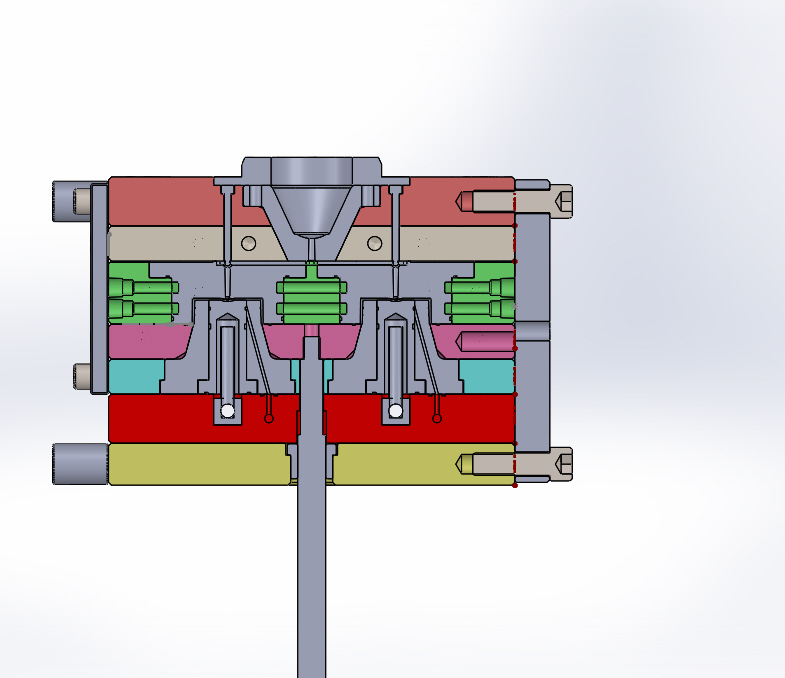
Interlocking Case Study
Figures 1 and 2 show two different interlocking design for a standard square food container part.


Both designs have a stripper plate which is used to eject the container off the core. The only difference between the 2 designs is the interlocking design on the stripper plate. Click here to learn more about stripper plates.
Which one would you use?
Which design is more likely to make poor quality parts and which one will give long term quality results?
In theory, both plastic injection mold designs should work. The problem is however, for both designs to work everything must be perfect. That is, all mould plates must be flat and free of damage. The machine platens must also be flat and free of damage. The machine tie bar stretch must be equal in all 4 tie bars – and this is usually not the case especially when machines have not been maintained properly.
Uneven tie bar stretch or any damage on the mould or platens will put the mould on a slight angle when clamp tonnage is applied creating sideways forces when the cavity is filled with plastic. If the interlock design does not allow for this, then the stripper plate will be forced open on one side creating a GAP and the parts will flash.
See figure 3 where interlock A forces interlock B to open allowing flash to occur.


However, figure 4 shows a design which will not allow flash even if the there is some sideways force because the gap is created on the other side at interlock C where there is no molding. In this tool design, any sideways force will act towards the centre of the mold so there is no way the stripper plate can be forced open. The force on interlock C is transferred to interlock D holding it closed on that side of the interlock.
This is a plastic injection mold design that will last for millions of cycles provided it is made correctly and properly maintained.
Additional Comments
The sideways movement I am writing about is so small that one cannot see it with the naked eye. It is a vibration. Placing a dial indicator on the mold might show the vibration. In any case, with time, the hard mark wear pattern on the shutoff faces of the core and cavity will show evidence of this movement.
The fact is, both of these designs are easy to make with standard toolmaking equipment but they give a profoundly different result for the molder. So it is critical that correct plastic injection mold design is used so that quality parts can be manufactured for the life of a mold.
Right-click here to download our latest mold design tip published in the 2014 spring edition of the Society of Plastics Engineers newsletter in PDF format.
Go to Page 22
"How Injection Mold Design Effects Part Quality"