- Home
- Lean Principles
- Machine Selection
- Mold Design
- Mold Interlocking
- Mold Making
- Plastic Material Technology
- Molding Process
- What's New
- Privacy Policy
- Disclaimer
- Site Map
- Poll
- Polishing
- 3D Rapid Prototyping
- Molding Companies
- Contact Us
- MOLD WEIGHT CALCULATOR
- HOT RUNNER VERSUS COLD RUNNER
- Industry Proven Mold Designs for Sale
Injection Mold Design - A Little Known But Costly Mistake
Correct injection mold design is crucial to having a profitable business. A proper design will ensure quality plastic parts will be produced for the intended life of the mould at the expected cycle time.
Correct injection mold design has the following benefits:
- Quick mold setups
- Faster cycle times
- Quality parts
- Low reject rate
- High productivity
- Long mold life
- Long molding machine life
- Higher employee morale
Unfortunately, many mold designs have some fundamental flaws which prevent the injection molder from achieving a higher level of productivity.
By learning about one of the most common injection mold design mistakes you can avoid waste and help make your company grow and be more profitable. Click here to learn about another common design mistake.
One of the Most Common Mistakes
Thin Back Plates
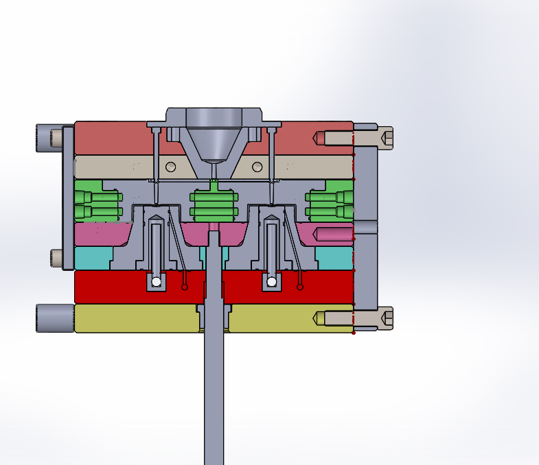
Most molds have 2 back plates with one on the fixed side and one on the moving side. Figure 1 shows the back plates in between the molding machines platens.
 Figure 1
The back plates have 3 main functions:
- To hold the mold in the moulding machine using clamps
- To form part of the runner system
- Support the entire mould against excessive platen deflection
If the back plates are too thin then the resultant repetitive deflection during each cycle eventually causes the following part quality problems:
- Flashing
- Shorting
- Weight variation
- Voids
- Sink
- Balancing issues
These quality problems occur because the platens do not provide enough support to stabilize the mould against cavity injection pressure and clamp tonnage.
What’s more, repetitive deflection causes wear inside the mould. One of the things mould wear does is reduce the effectiveness of the venting. Poor venting will also result in reject parts – especially in multi cavity moulds.
It’s important to keep in mind that during the injection molding process most machines will have some amount of platen deflection. Platen deflection is not necessarily a bad thing, however, if the deflection is extreme then part quality will deteriorate over time. This can happen over a period of years, months or weeks depending upon the injection mold design and selection and condition of the moulding machine.
Platen deflection is usually worse on the fixed side platen because of the weakness created by the location ring diameter and the larger recess behind it. The diameter is quite large in most machines as it is clearance to allow the machine injection unit nozzle to connect to the mould (see figure 1).
On top of that, if the fixed half of a mold is a cavity (as opposed to a core) then this adds to the weakness of the system. A cavity is naturally weak because of its shape.
The combination of these 2 weaknesses require an extra thick and wider back plate on the fixed side to strengthen a mold.
Case Study

Figure 2 is a rectangular lid made from a 2 cavity mold. The lid started to severely flash after only 8 weeks from mould commissioning. An investigation found that there was too much platen deflection so the fixed side back plate was replaced on the mold.
The original plate was 90mm (see figure 5) while the new plate was 150mm. The thicker back plate bought the deflection within a manageable level so that quality problems were eliminated.
The main clue to the problem was the pattern of radial brown hard marks found on the back plate – see figure 3. This pattern was a clear indication of too much platen deflection causing the mould to wear on the shut off faces of the cores and cavities resulting in part flash. Figure 4 gives a closer view of the hard marks.


Additional Comments

Relating part quality problems to excessive platen deflection is not that difficult once you know where to look and what to look for.
This type of issue happens in all types of injection moulds from fast cycling thin wall moulds to slow cycling single cavity moulds and the sign is the same for all of them.
Look for radial lines of hard marks on back plates and also on shut off surfaces of cores and cavities.
Figures 6, 7 and 8 are more examples of the hard mark pattern produced when large platen deflection is present.


Example of Good Injection Mold Design

Figures 9, 10 and 11 show a 4 cavity lid mold designed with an extra thick back plate on the fixed side 150mm thick.
This mould has produced millions of quality parts without any problems. Note the hard mark pattern on the back plate in figure 9, it is completely different to the pattern in the 2 cavity (figure 3).
This is how the hard marks on a properly designed mould should be.
Click here to learn how to improve mold design using moldmax copper alloys.


Click here to learn more about another aspect of mold design called 3 plate mold design.
Have a Question About Injection Mold Design?
Are you having difficulties with mold design? Need help selecting the right steel? Not sure how to design a reliable ejector system?
This is the place where you can ask your question about mould design..
Ask a question and get your free 5 page troubleshooting pdf guide to eliminating short shots plus an 8 page pdf guide to eliminating flash. In addition to this, get my mold design checklist which will ensure you will never forget the important aspects of design.
The pdf files will be available after submission for immediate download. No email address required.
What Other Visitors Have Asked
Click below to see contributions from other visitors to this page...
Ejecting of the lid
Is it better to eject the lids (inside injected) by the stripper ring (plate) that is powered by hydraulic or pneumatic cylinder?
Tooling Dept.
I have a 3 plate mould with 4 cavities and an angular slider in each cavity, at less than 50k shots the slider breaks, What can i do to improve the slider …
carlos ramos
do you have an online course?
Learning Injection molding design
when wearplate is designed, is it necessary that there should be a very small gap between the core and cavity side of the mold right where the wearplate …
Clamp plate thickness
How can we calculate the minimum thickness o clamp plate to avoid bad design?
Isolate plates
Where is better to put isolate during mold design? inside mold (between clamp plate and cavity plates) or outside? (after clamp plate)
Can be an important …
Ketan
How to avoid weld lines.
mold size calculation
From part size & number of sliders,undercut how to calculate tentative mold size?
What’s would be the extra material to keep at the matching area of core and cavity inserts
1What’s would be the extra material to keep at the matching area of core and cavity Inserts
2. How to provide spacer lengths interms of ejection length …
Support pillars
Is there any specific calculation for using a particular size of support pillars and it's placing?
Gas vent
How to improve gas vent for part having mirror face?
Life of a wear plate
How long is the maximum life of a wear plate?
Answer:
The purpose of a wear plate in an injection mould is to act as a sacrificial component in preference …
Gate Type & Mold Steels
Question by Mohamed: How to choose the correct gate type and the correct mold steel?
Answer:
The type of gate depends upon a number of factors …
Nox-Rust Paper
Question: What problems other than a visual indicator could be caused by using nox-rust paper on the back plates of injection molds?
My answer:
…
Two Plate Mould Design
Question by Satyajit: How to design a two plate injection mould?
My answer:
The 2 plate plate mould has one parting line opening as opposed to …
Details about core cavity seating
Question by Rajesh: How to make a core and cavity to accurate seating,details about guide pillar bushes assembly.
My Answer:
To get accurate seating …
Dimensional Stability
What guidance do you have for achievable limits on DST injection urea machines regarding the number of cavities that can be reliably balanced to give dimensional …
What do you think of diamond coatings used on molds?
I am wondering what your experience has been using diamond coatings on molds. Some coating enhance ejection so help with galling. Do you have experience …
Location rings
Can this be eliminated on a mold?
Why do some groups use or not use?
-Sam
Answer:
A location ring can be eliminated on a mold BUT it is …
Family molds
Whats your thoughts on family molds?
Answer:
You must know what you are doing when designing family moulds.
The runner channel should give balanced …
Gate Location
Where is the best position to put the gate?
Answer:
Design guidelines.
Locate the gate in:
1. the thickest wall section so that hold pressure …
Stripper plate ejection: Hydraulic or Pneumatic?
Should I use hydraulics or pneumatics for stripper plate movement?
Answer:
The easiest way to move a stripper plate in an injection mold is by using …
Nitriding
In what applications would nitrding surface treatment be used?
Nitriding is useful for moving components in a mould.
Typical applications include …
Mold material
What material is best to build a mold with?
Answer:
The mold material mainly depends upon the annual shot quantity requirement. But it also depends …
Hot runner or Cold runner
Which is better, cold runner or hot runner?
Barry,
It really depends upon your annual quantity requirements. If producing more than one million a …


