- Home
- Lean Principles
- Machine Selection
- Mold Design
- Mold Interlocking
- Mold Making
- Plastic Material Technology
- Molding Process
- What's New
- Privacy Policy
- Disclaimer
- Site Map
- Poll
- Polishing
- 3D Rapid Prototyping
- Molding Companies
- Contact Us
- MOLD WEIGHT CALCULATOR
- HOT RUNNER VERSUS COLD RUNNER
- Industry Proven Mold Designs for Sale
Setting Hold Time and Hold Pressure to Run an Optimized Process
Setting Hold Pressure
Before setting up your hold pressure, be sure that your part (most filled part for multi-cavity) is roughly 95-98% filled by volume. Utilizing high injection pressure to fill the cavity to 100% or to the point where the part is being packed with injection pressure can cause a pressure spike that can incur serious damage to the tool if constantly repeated. After you determine your optimum injection velocity, be sure to adjust your shot size and/or transfer position to ensure the part is still 95-98% filled by volume.
When setting up a two-stage optimized process, packing pressure is used to fill the remaining unfilled portion of the cavity and to compensate for material shrinkage. This is done at a much lower pressure compared to the injection pressure, usually 50–80% of the injection pressure at switchover. To determine your optimum hold pressure, start at a very low hold pressure, between 1,000 and 2,000 psi plastic pressure. Increase the hold pressure by 500 or 1,000 psi plastic pressure until you have full part without any sink marks or signs of an “unfilled” part.
Once you have determined the minimum hold pressure required to make an acceptable part, continue to increase the hold pressure until you notice flash or are encountering other tooling issues such as cavities sticking. This will be considered the maximum hold pressure. As a general rule of thumb, taking the average of the minimum and maximum hold pressure determined earlier will give you your optimum hold pressure. By setting the hold pressure between the two extremes, this minimizes your chances of encountering visual defects shot-to-shot although slight adjustments may still be made to this optimum value if necessary.
Some things to consider:
- If setting up a multi-cavity tool, evaluate the most filled part if there is a cavity-to-cavity filling imbalance.
- If the parts are evaluated as being too large or too small, this could indicate the steel was cut to the wrong dimensions.
- If the parts are sticking or there is a very small hold pressure window, this could indicate poor gate design (thin to thick), insufficient draft angle to release the part, or insufficient clamp tonnage
A critical parameter to check after setting your hold pressure is your cushion. Cushion is the remaining plastic left over after your hold time ends. If your cushion is at zero, this indicates that your screw is pushing on metal and not on plastic. By having no cushion, you have essentially “bottomed-out” the screw so there is no force being generated on the plastic to pack out the part. Generally, you want a cushion of 0.10 to 0.25 inches to minimize material degradation. You can increase the transfer position and your shot size by the same amount to increase your cushion.
Setting Hold Time
Hold time is the duration in which the hold pressure is applied. During this time, a constant pressure is applied to compensate for material shrinkage by pushing more molten plastic into the cavitation. Once the gate is frozen, however, molten plastic can no longer reach the cavitation and the remaining time is spent packing out the runner system. This not only wastes energy, but can possibly increase your cycle time. With cycle time being a critical component, performing a gate-seal study is common method to determine the time in which the gate freezes to reduce cycle time. Gate-seal studies are common for most cold-runner molds, but they are not practical for either hot-runner nor valve-gated systems.
To perform a gate-seal study, once you have determined your optimum hold pressure, estimate a time in which the gate freezes and set the hold timer a few seconds above that time. For example, if you think the gate freezes at 6.0 seconds, set the hold time to roughly 10 seconds to begin the study. After each shot, collect and weigh each part, then record the data. For multi-cavity tools, weigh each part individually as the gate seal variation between cavities can indicate tooling issues. After each shot, reduce the hold time by 1.0 second and increase the cooling time by 1.0 second to keep a consistent cycle time. Repeat this process until you have collected samples from roughly 10 shots. After collecting all the data for this study, it is common to plot the results in a “part weight” versus “hold time” line plot to determine your gate-seal time as shown below.
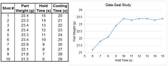
After analyzing the graph, you can see that the weight of the part begins to remain consistent at a hold time of 10 seconds, this would be considered the time your gate is sealed. After determining your gate-seal time, 0.5 to 1.0 seconds should be added to achieve your new optimized hold time. The additional 0.5 to 1.0 seconds is added as a safety factor to ensure the gate is sealed after each shot to minimize shot-to-shot variation.
Article written by: Elite Machinery Systems LLC. Sellers and buyers of used injection molding machines. Visit their website at www.elitemachinerysystems.com (opens in a new window)
References:
J. P. Beaumont, Runner and Gating Design Handbook: Tools for Successful Injection Molding. Germany: Carl Hanser Verlag GmbH & Co, 2004.
J. Bozzelli, "Injection Molding: How to Set Second-Stage (Pack & Hold) Pressure," in Plastics Technology, 2011. [Online]. Available:www.ptonline.com/columns/how-to-set-second-stage-pack-hold-pressure (7). Accessed: Aug. 16, 2016.